Metal Nano Molding Process: Enabling High-Precision Micro-Metal Components
Jan 07, 2026
Overheating is one of the most common challenges in modern electronic product development. As electronic devices become smaller, more powerful, and more integrated, the heat generated by internal components becomes increasingly difficult to manage. Excessive temperatures can reduce performance, shorten component lifespan, cause unexpected shutdowns, and affect product reliability.
Traditional cooling methods, such as adding heat sinks, increasing ventilation, or using thicker metal housings, may help in some situations. However, these approaches do not always address the root cause of a thermal problem. Without understanding how heat moves through a product and how airflow behaves inside an enclosure, design changes can become a process of repeated trial and error.
Advanced thermal simulation design offers a more practical approach. By evaluating temperature distribution, heat transfer, and airflow before manufacturing, engineers can identify potential overheating problems early and develop cooling solutions that fit the actual operating conditions.
For manufacturers such as SOGOOD, which integrates product design, thermal simulation, precision hardware manufacturing, and heat dissipation solutions, thermal analysis is an important part of developing reliable electronic products.
Before selecting a cooling solution, engineers need to understand why a product generates or retains excessive heat. Different applications may experience similar temperature problems for very different reasons.
Processors, power modules, communication chips, LED drivers, and other electronic components generate heat during operation. As processing speeds and power densities increase, the amount of heat concentrated in a small area can become significant.
For example, an AI computing module may contain several high-power components arranged closely together. Even if each component operates within its individual limits, the combined heat load can create local hot spots that affect nearby components.
Compact product design creates another challenge. A smaller enclosure leaves less room for air circulation and reduces the space available for heat sinks, fans, and other cooling components.
Internal structures can also obstruct airflow. Cables, mounting brackets, circuit boards, and structural ribs may create stagnant areas where hot air accumulates. A cooling design that works well in an open test environment may therefore perform poorly after the product is fully assembled.
Heat must travel from the heat-generating component to a surface where it can be released into the surrounding environment. This path may include a thermal interface material, a metal base, a heat sink, and the enclosure itself.
If any part of this path has excessive thermal resistance, heat transfer becomes less effective. Uneven contact surfaces, insufficient mounting pressure, unsuitable interface materials, and poorly designed structural connections can all contribute to overheating.
These issues are difficult to evaluate through external temperature measurements alone. Thermal simulation helps engineers examine the complete heat-transfer path rather than focusing only on the final surface temperature.
Thermal simulation uses engineering models to predict temperature distribution and heat transfer under defined operating conditions. Depending on the product, the analysis may include conduction, convection, radiation, or a combination of these mechanisms.
Computational fluid dynamics (CFD) is commonly used when airflow and convective cooling are important. Finite element analysis (FEA) can help evaluate heat conduction through solid components and structural assemblies.
A practical thermal simulation workflow generally includes the following steps.
Engineers begin with the product's three-dimensional geometry, including the enclosure, circuit boards, major heat-generating components, heat sinks, and relevant mounting structures.
The model should retain the features that influence heat transfer while simplifying details that have little thermal impact. Excessively detailed geometry can increase computational requirements without necessarily improving the usefulness of the results.
For precision electronic housings, the material properties of aluminum alloys, interface materials, plastics, and other components should also be defined appropriately.
A simulation is only as useful as its input data. Engineers need to estimate or measure the heat generated by each major component, the ambient temperature, the expected airflow, and the thermal properties of the materials.
For a passively cooled device, natural convection and the available surface area may dominate its thermal performance. For a fan-cooled communication enclosure, airflow rate, fan characteristics, inlet and outlet locations, and internal pressure losses may be more important.
Engineers should also consider the most demanding operating conditions, such as high ambient temperatures, sustained workloads, or restricted ventilation.
Once the model and boundary conditions are established, the simulation calculates how heat moves through the product.
Temperature contour maps help identify hot spots, while airflow visualizations show whether air reaches the components that need cooling. Engineers can also examine temperature gradients across metal structures and assess whether heat sinks are using their available surface area effectively.
These results provide a clearer explanation of why overheating occurs and which design changes are likely to make a measurable difference.
Simulation should not replace physical testing. Instead, it should guide the design process and help engineers make better use of prototype testing.
Temperature measurements from thermocouples, infrared cameras, or other suitable instruments can be compared with simulation results. Differences may reveal incorrect heat-load assumptions, inaccurate material properties, unexpected contact resistance, or unmodeled airflow restrictions.
This validation step improves confidence in subsequent design iterations.
Heat sinks are widely used in electronic devices, industrial equipment, automotive electronics, and communication systems. However, simply increasing their size or adding more fins does not guarantee better cooling.
Thermal simulation helps engineers evaluate several design variables before committing to tooling or production.
Increasing the number of fins can expand the available heat-transfer area. However, fins placed too closely together may restrict airflow, particularly in forced-air cooling systems.
Simulation can compare fin height, thickness, spacing, and orientation to determine which configuration provides a suitable balance between surface area and airflow resistance.
Aluminum is widely used for heat sinks because it offers a practical combination of thermal conductivity, low weight, corrosion resistance, and manufacturability. Copper may be suitable for applications requiring higher thermal conductivity, although its greater density and manufacturing considerations can limit its use.
Thermal simulation allows engineers to compare candidate materials within the same product geometry and operating environment.
The connection between a component and its heat sink can significantly affect overall performance. A high-performance heat sink cannot compensate for poor thermal contact.
Engineers should evaluate the contact area, mounting arrangement, flatness requirements, and thermal interface material. In some cases, improving the interface can provide more benefit than redesigning the heat sink itself.
By examining these factors together, simulation supports a more targeted approach to thermal optimization.
An enclosure is more than a protective shell. Its geometry, material, internal layout, and external surface area can all influence heat dissipation.
For sealed electronic products, engineers face a particular challenge: the enclosure must protect internal components from dust, moisture, or other environmental conditions while still allowing heat to escape.
Thermal simulation can help determine whether the housing should act as a passive heat spreader, connect directly to a heat-generating component, or incorporate additional thermal structures.
For example, an aluminum enclosure with an integrated heat sink may reduce the need for separate cooling components. However, its effectiveness depends on the internal thermal path, the external environment, and the product's installation conditions.
Engineers can compare alternative wall thicknesses, mounting locations, fin arrangements, and internal component layouts before finalizing the design.
This is especially valuable when a product has strict dimensional requirements. Instead of enlarging the entire housing to solve a temperature problem, the engineering team can focus on the specific areas responsible for excessive thermal resistance.
For manufacturers developing customized housings, brackets, heat sinks, and precision metal parts, integrating thermal analysis with mechanical design helps balance cooling performance, structural requirements, and manufacturability.
A successful thermal design must be manufacturable as well as effective in simulation. This is where close coordination between engineering analysis and production becomes important.
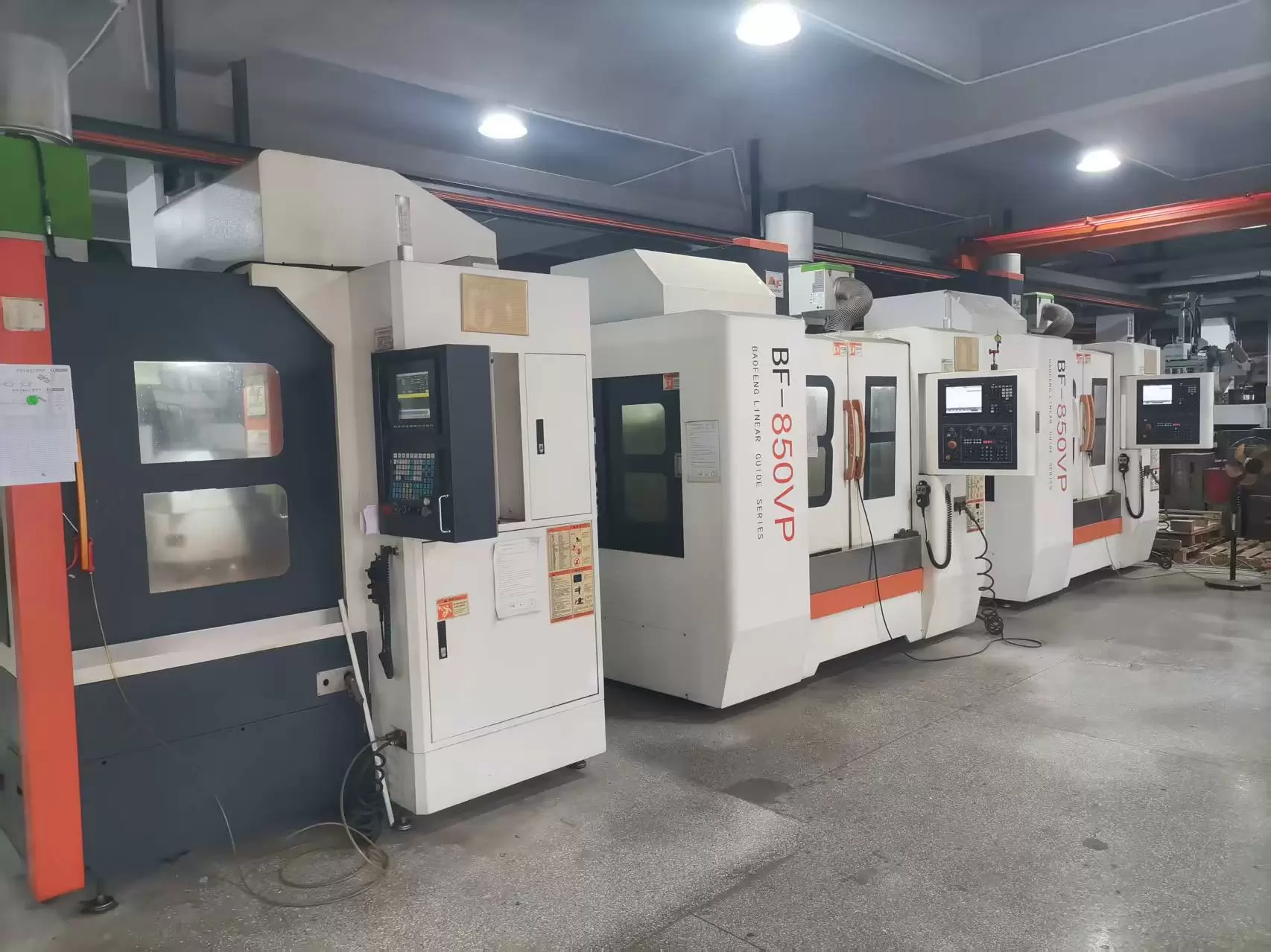
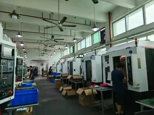
CNC machining is suitable for producing precision aluminum housings, heat sinks, mounting structures, and customized thermal components. It supports accurate dimensional control and allows engineers to refine critical surfaces, mounting interfaces, and complex geometries.
When thermal analysis identifies a problem around a component contact area or heat-spreading structure, CNC machining can help implement the required design changes in a prototype or production part.
Machining also makes it possible to evaluate different design versions without immediately committing to a dedicated mold.
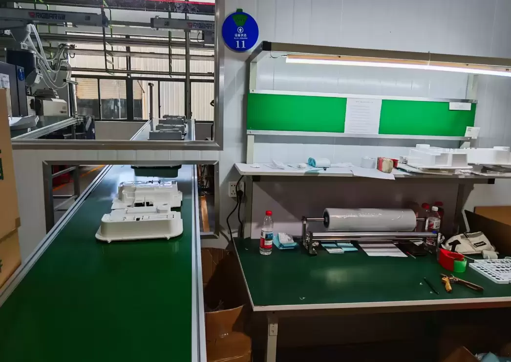
Metal nano molding technology can combine metal components with selected engineering plastics through a specialized molding process. Depending on the application and material system, this approach can support compact structures, functional integration, and distinctive product designs.
For electronic products that require both metal strength and plastic design flexibility, the technology may help reduce the number of separate parts and simplify assembly.
However, metal nano molding is not automatically a thermal solution. Engineers must evaluate the thermal conductivity of each material, the geometry of the metal section, and the location of heat-generating components. Plastic regions may interrupt heat conduction if the design does not provide an appropriate thermal path.
Combining simulation, material selection, and manufacturing process evaluation helps determine whether this technology is suitable for a particular application.
SOGOOD integrates thermal simulation design with precision manufacturing capabilities to support the development of customized metal components, enclosures, accessories, and heat dissipation structures. More information about its manufacturing capabilities is available through its precision manufacturing and engineering services.
Thermal simulation design is useful across a wide range of industries, although each application presents different priorities.
Consumer electronics: Compact housings and closely arranged components require careful control of hot spots and surface temperatures.
Telecommunications: Network equipment and communication modules may operate continuously, making stable thermal performance essential for reliability.
Automotive electronics: Electronic control units and power-related components must manage heat under changing ambient temperatures, vibration, and demanding operating conditions.
Medical devices: Thermal design must account for product safety, operating stability, and application-specific requirements for external and internal temperatures.
AI and computing equipment: High-power processors and accelerators create concentrated heat loads that may require coordinated heat sinks, heat spreaders, and airflow management.
In each case, simulation should reflect the actual installation environment. A component cooled effectively in a laboratory may behave differently when installed in a sealed cabinet, exposed to direct sunlight, or surrounded by other heat-generating equipment.
To obtain useful results, engineering teams should follow several practical principles.
First, use measured power consumption and realistic operating conditions whenever possible. Assumptions that are too optimistic can produce misleading temperature predictions.
Second, prioritize the thermal path from the heat source to the surrounding environment. Improving one critical interface may be more effective than adding cooling features throughout the product.
Third, compare several design alternatives rather than relying on a single simulation. Small changes in fin spacing, material thickness, component placement, or airflow direction can produce meaningful differences.
Fourth, consider manufacturing limitations early. Extremely thin fins, difficult-to-machine cavities, complex interfaces, and unnecessary assembly steps can make a design harder to produce consistently.
Finally, verify the final design through physical testing. Simulation results should be checked against the prototype under representative operating conditions before the product enters mass production.
Solving overheating issues requires more than adding a larger heat sink or increasing ventilation. Reliable thermal performance depends on understanding heat generation, conduction paths, airflow, enclosure geometry, material properties, and actual operating conditions.
Advanced thermal simulation design gives engineers a way to evaluate these factors before manufacturing, identify hot spots, compare cooling strategies, and reduce unnecessary design changes. When combined with CNC precision machining, appropriate material selection, and manufacturing-oriented product development, it becomes a practical tool for improving product reliability and production readiness.
SOGOOD brings together product design, thermal simulation, precision hardware manufacturing, metal nano molding technology, and CNC machining to support customers developing electronic housings, heat sinks, and customized components. With engineering experience and an ISO 9001-certified quality management system, SOGOOD welcomes OEM and ODM projects that require coordinated development from design evaluation to manufacturing.
For businesses facing thermal challenges in new or existing products, the most effective starting point is to evaluate the heat source, the thermal path, and the available cooling space together. A well-validated thermal design can help transform an overheating problem into a manageable engineering solution.